

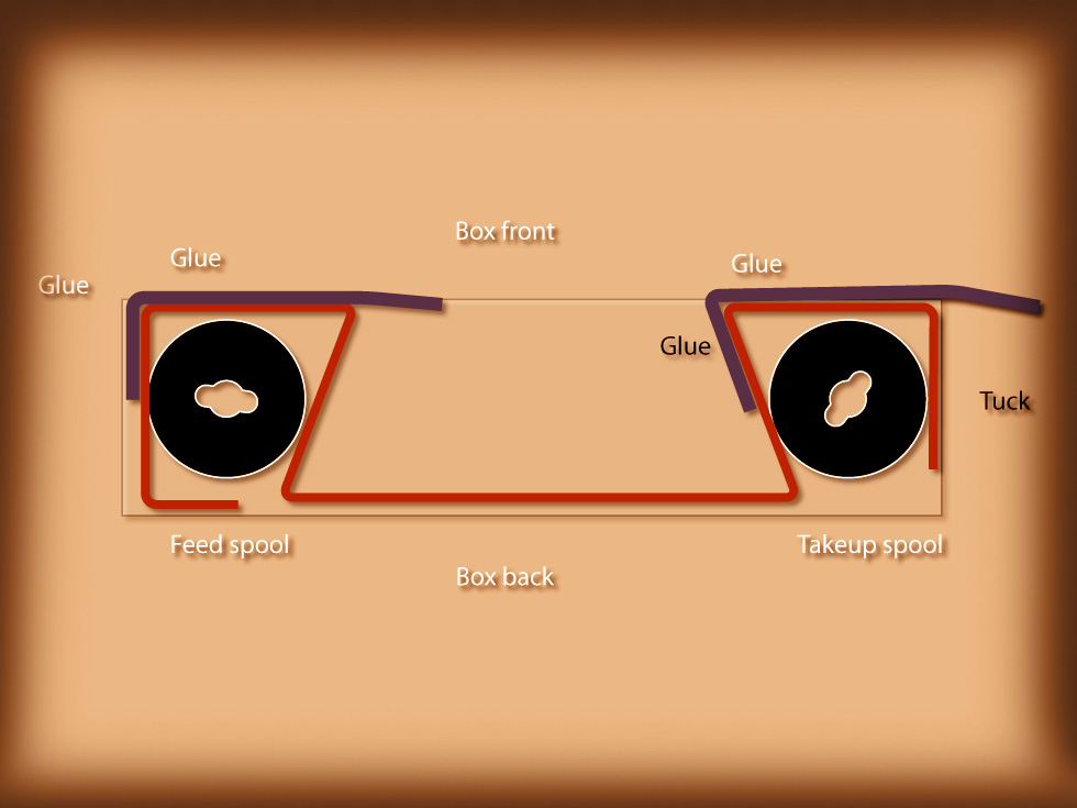
Image 11 – A – Film Path – Showing baffles
As I stated in the first two related postings, one of my to-do projects for WPPD 2012 was to build a working 120 pinhole camera from a large kitchen matchbox.
This is the fourth of a number of posts that will be devoted to the construction and the use of such a camera.
Although I have built smaller 35mm pinhole cameras from regular matchboxes, I had never built one with this size matchbox until I got the idea a couple of years ago. While the first one worked pretty well, I have decided to make a few minor alterations in order to make the camera a little more durable.
So, in that sense, it will be a work in progress.
PLEASE READ! – As this is a learn-as-I-go project, I will not post this as a single post tutorial. I am showing you my progress in the hopes of getting you interested in the building process. In the end, you can follow through the links that will show you the complete step-by-step build. To see previous posts use the links below.
Here is where I am at the moment with Part 4:
To date, I have finished the light proofing on the back portion and designed the beginnings of a film advance.
With this post I am adding a front light baffle to the insert.
The most important part of making any camera, is making sure that stray light is not allowed to enter through cracks or holes. A couple of light baffles added to the front, will keep out any unwanted light.
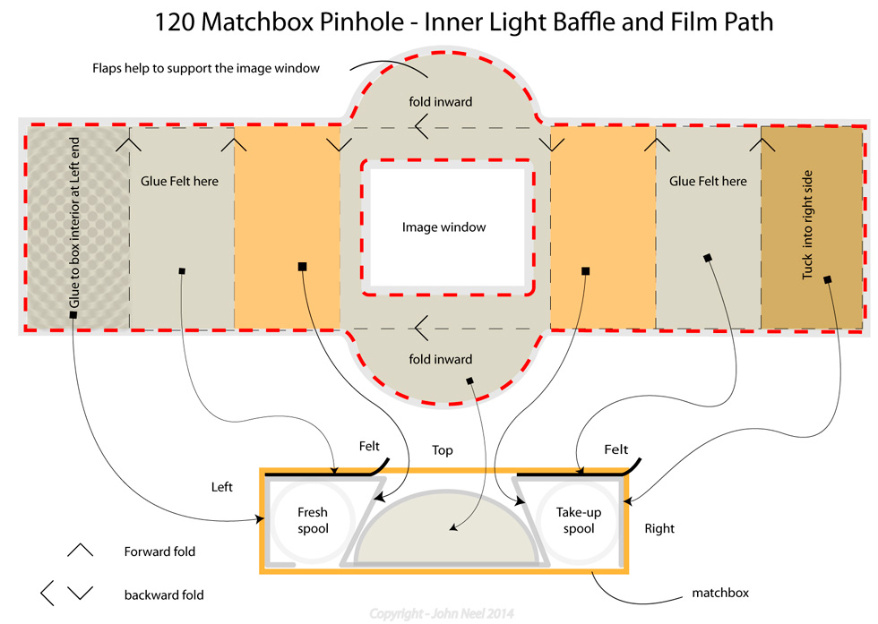
The interior schematic
Here is a downloadable pdf that will act as a template for this portion of the build. Matchboxtemplate
Note: The board used for creating the baffle must be fairly stiff in order to work without collapsing the camera due to friction during the winding process. Also, the measurements should be snug fitting but not so much as to cause binding during the winding process. The dimensions will probably vary depending on the actual size of the matchbox being used. Scoring the fold points will help produce a straight fold.
Note: As matchboxes are very likely to be slightly different in size, you might need to modify the template to the one you are using. The template is scaled to the one I am producing.

Image 11 – B – Folded baffle
Image 11 – A (above) and B – This shows how the interior is folded in order to hold the film spools in place. The two heavy dark lines show where the felt is used to act as a light tight baffle. The thin pale line is the inner box shown from the side. Here I show the film spools with the new roll on the left and the take-up on the right.
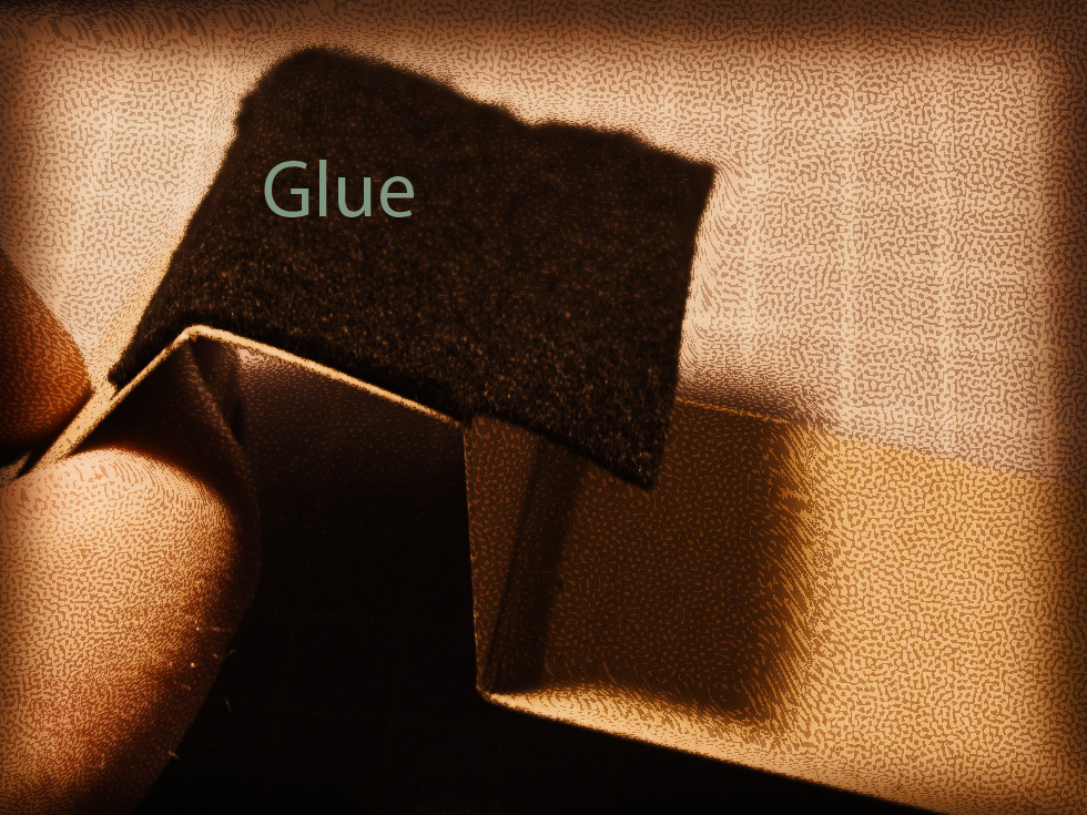
Image 12 – Left side light baffle
Image 12 – Here is the left side of the insert with the black felt glued to the second and third section. The felt is allowed to overhang loosely over the fourth section.
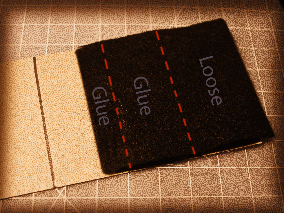
Image 13 – Right side light baffle
Image 13 – Felt is also glued to the right side of the insert as shown. The felt should be glued down starting at the fifth section and needs to be long enough to extend outside the end of the box when finished.
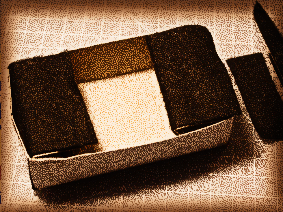
Image 14 – Both baffles in place
Image 14 – The folded insert shown with the two pieces of felt glued in place.
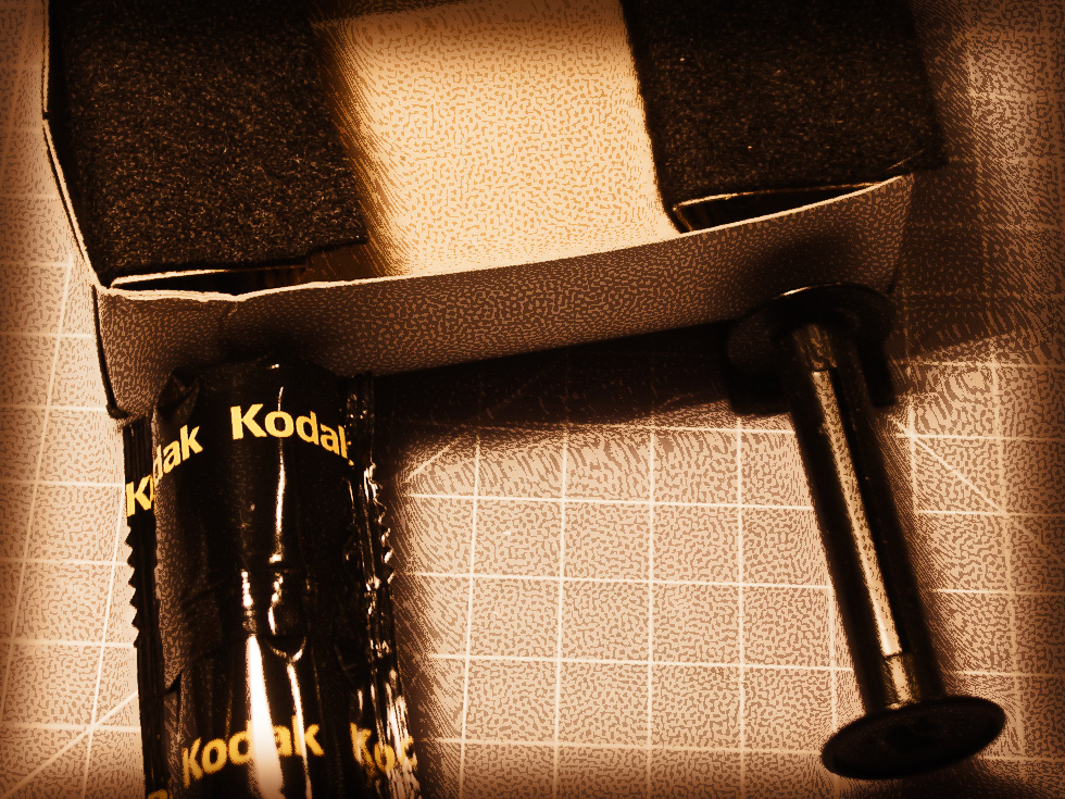
Image 15 – film and take-up spool positions
Image 15 – Film will eventually be loaded with the take-up spool to the right ” Side B” and the new film spool ” Side A” to the left when looking down.
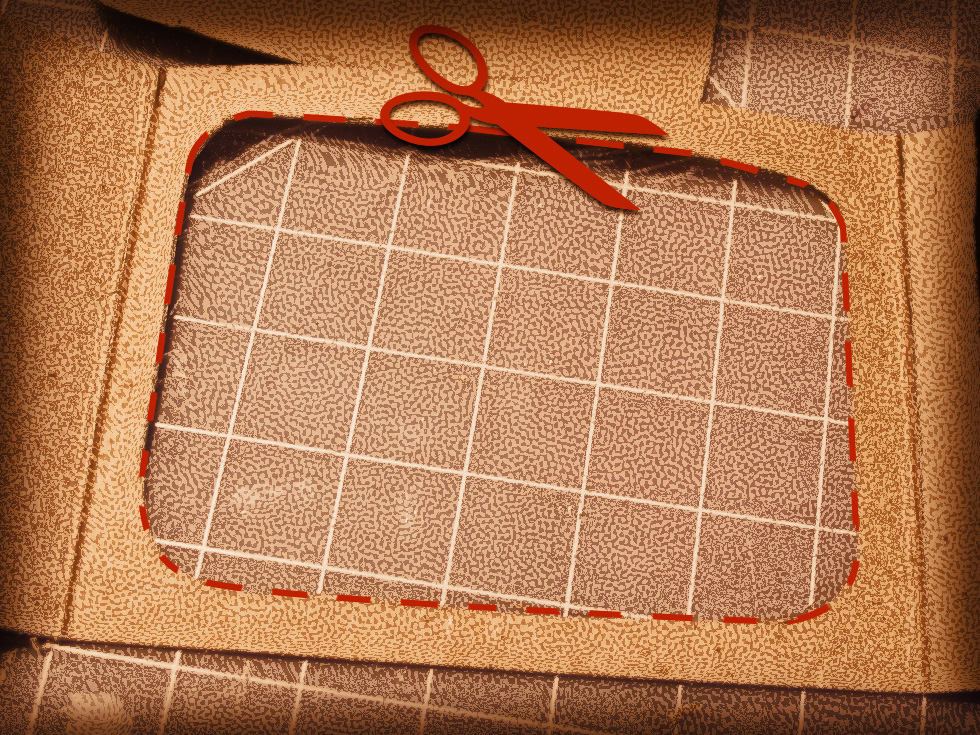
Image 16 – Film gate
Image 16 – The cutout shown here is the area that will act as the film exposure frame (film gate or image window). The shape can be almost anything you like. Remember that the image will be formed upside down when shooting pictures. In this case, I am using a rounded rectangle that will produce images with rounded corners.
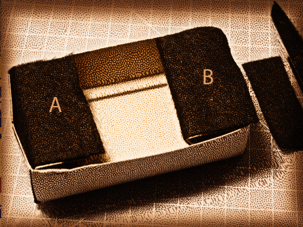
Image 17 – baffle in place showing film gate
Image 17 – The insert is shown here folded and placed into the inner box. The felt on the left side A should protrude into the center opening. The felt on the right side B should protrude over the edge of the right end of the box. This will allow the inner box to easily slide into the outer shell and seal the seams in the process.
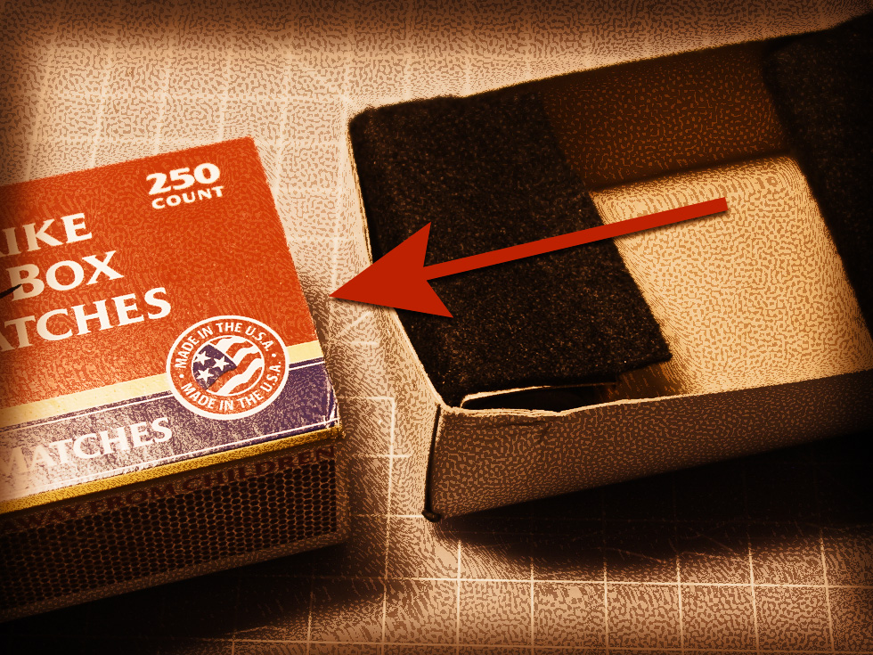
Image 18 – Insert inner box into outer shell
Image 18 – With everything folded and in place, the inner box is inserted into the matchbox sleeve “A Side” first as shown. At this point we are simply checking for fit.
There are still a few steps left to complete this project and to make this a fully functional camera. I will cover them in the next several posts.
Here is a downloadable pdf that will act as a template for this portion of the build. Matchboxtemplate
Are You Ready? The next pinhole day is April 27, 2014
120 Matchbox Pinhole Project – Part 1
120 Matchbox Pinhole Project – Part 2
120 Matchbox Pinhole Project – Part 3

Rethinking Digital Photography – John Neel
My book – Rethinking Digital Photography
Read more about Pinhole Photography and other great photographic techniques in my book Rethinking Digital Photography.
NOTICE of Copyright: THIS POSTING AS WELL AS ALL PHOTOGRAPHS, GALLERY IMAGES, AND ILLUSTRATIONS ARE COPYRIGHT © JOHN NEEL AND ARE NOT TO BE USED FOR ANY PURPOSE WITHOUT WRITTEN CONSENT FROM THE WRITER, THE PHOTOGRAPHER AND/OR lensgarden.com. THE IDEAS EXPRESSED ARE THE PROPERTY OF THE PHOTOGRAPHER AND THE AUTHOR
